Production Machining - Your access to the precision machining industrial buyer.
Issue link: https://pm.epubxp.com/i/668041
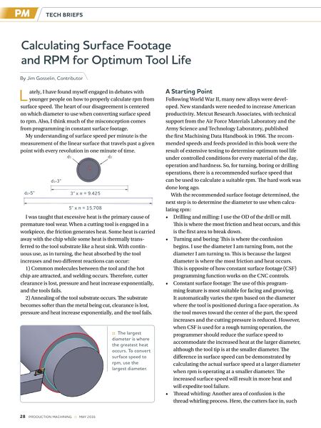
Calculating Surface Footage and RPM for Optimum Tool Life By Jim Gosselin, Contributor :: The largest diameter is where the greatest heat occurs. To convert surface speed to rpm, use the largest diameter. d1 d2 d1=3" d 2=5" 3" x π = 9.425 5" x π = 15.708 TECH BRIEFS 28 PRODUCTION MACHINING :: MAY 2016 L ately, I have found myself engaged in debates with younger people on how to properly calculate rpm from surface speed. Te heart of our disagreement is centered on which diameter to use when converting surface speed to rpm. Also, I think much of the misconception comes from programming in constant surface footage. My understanding of surface speed per minute is the measurement of the linear surface that travels past a given point with every revolution in one minute of time. I was taught that excessive heat is the primary cause of premature tool wear. When a cutting tool is engaged in a workpiece, the friction generates heat. Some heat is carried away with the chip while some heat is thermally trans- ferred to the tool substrate like a heat sink. With contin- uous use, as in turning, the heat absorbed by the tool increases and two diferent reactions can occur: 1) Common molecules between the tool and the hot chip are attracted, and welding occurs. Terefore, cutter clearance is lost, pressure and heat increase exponentially, and the tools fails. 2) Annealing of the tool substrate occurs. Te substrate becomes softer than the metal being cut, clearance is lost, pressure and heat increase exponentially, and the tool fails. A Starting Point Following World War II, many new alloys were devel- oped. New standards were needed to increase American productivity. Metcut Research Associates, with technical support from the Air Force Materials Laboratory and the Army Science and Technology Laboratory, published the frst Machining Data Handbook in 1966. Te recom- mended speeds and feeds provided in this book were the result of extensive testing to determine optimum tool life under controlled conditions for every material of the day, operation and hardness. So, for turning, boring or drilling operations, there is a recommended surface speed that can be used to calculate a suitable rpm. Te hard work was done long ago. With the recommended surface footage determined, the next step is to determine the diameter to use when calcu- lating rpm: • Drilling and milling: I use the OD of the drill or mill. Tis is where the most friction and heat occurs, and this is the frst area to break down. • Turning and boring: Tis is where the confusion begins. I use the diameter I am turning from, not the diameter I am turning to. Tis is because the largest diameter is where the most friction and heat occurs. Tis is opposite of how constant surface footage (CSF) programming function works on the CNC controls. • Constant surface footage: Te use of this program- ming feature is most suitable for facing and grooving. It automatically varies the rpm based on the diameter where the tool is positioned during a face operation. As the tool moves toward the center of the part, the speed increases and the cutting pressure is reduced. However, when CSF is used for a rough turning operation, the programmer should reduce the surface speed to accommodate the increased heat at the larger diameter, although the tool tip is at the smaller diameter. Te diference in surface speed can be demonstrated by calculating the actual surface speed at a larger diameter when rpm is operating at a smaller diameter. Te increased surface speed will result in more heat and will expedite tool failure. • Tread whirling: Another area of confusion is the thread whirling process. Here, the cutters face in, such